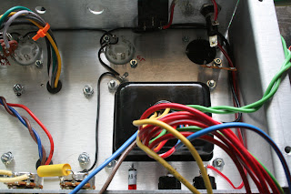
In my last entry, I talked about how my Marshall hodge-podge clone, that I lovingly named "Katie" died mid recording session, and how I am now fully vested in nursing her back to health again. I'm not too sure how many guitar players get to see (or really are interested in seeing) the innards of the box that makes all their noise possible, but I decided it would be a cool thing to document the deconstruction and reconstruction of my personal noise making box.
The Lightbulb Limiter
 |
| Fig. 1: The Lightbulb Limiter. |
Before pulling the amp completely apart, I had to run some tests with live electricity running through the amp just to see what had gone wrong. I had suspected some part(s) of the circuit had shorted, causing the mains fuse to blow, cutting off electricity to the entire amp. In order to run diagnostics on the amp, I installed a new fuse and then built a "lightbulb limiter." This crude device limits current by putting a lightbulb in series with the amplifier, so all electricity flows through the lightbulb before hitting the amplifier.
If you are interested, the lightbulb limiter works on the wattage principle:
Watts = Voltage x Current
where if you take an X watt lightbulb divided 120 volt line voltage coming off the wall will equal the total amperes of current available to whatever device you have plugged in downstream of the lightbulb (in series).
For example... 150 watt bulb / 120 volts = 1.25 amps
For the actual diagnostic I used a 75W bulb, limiting the current to 0.625A, well below the value of the mains fuse, so the fuse would no blow if there were any shorts.
I constructed the lightbulb limiter from:
-plastic wall lamp holder
-2 gang utility box
-dual wall outlet
-single three-way light switch
-plastic outlet/switch wall cover panel
-tool replacement power cable
-75 watt lightbulb
-14 AWG stranded wire
If any of you would like a schematic and/or layout of the limiter, just email me.
Trouble, trouble, trouble.
With the 75 watt bulb in place I plugged the amp into the limiter outlet and flipped the on switch on the limiter, then on the amp (with the amp still on standby) and found a problem right away. If nothing is wrong with the amp, the light should no glow at full brightness, indicating that the amp is not drawing excessive current, but the light lit up to full brightness, even with the amp on standby. This indicates a short on the primary winding. The primary of any power transformer should read around 115 to 120 volts in the States, but only read 2.5 volts on the multimeter. The short in the primary probably caused a huge current spike to occur through the rest of the amp, causing some of the damage to smoothing capacitors before the fuse blew.
 |
| Fig. 2 Burnt KT66 tube. |
Another issue was the burned tubes. I'm not sure if the power transformer failure caused the tubes to burn, or vice-versa, but somehow I think they are related events. I had heard that power tube failure can sometimes cause a power transformer failure as well. In my amp, this makes perfect sense if the problem originated at the power tubes first, being that I had these in my amp for nearly six years (stupid me!) and I never checked up on them to see if they needed replacing or drifted out of bias. Stupid of me; I will definitely never let that happen again.
The Cleanup.
 |
| Fig. 3: Main circuit board with old cloth wires. |
So began the cleanup. I first removed the two circuit boards and their connective wires, then tested each part with a multimeter, marking on the schematic with a highlighter which components were suspect for either damage or otherwise not reading their intended value, reserving the suspect components in a small jewelry organizer.
 |
| Fig. 4: Staying organized. |
I eventually had to remove almost everything from the chassis to take out the failed transformer.
 |
| Fig. 5: Cleaned up chassis. |
 |
| Fig. 6: The dead transformer, which had a good run for a time. You did good, kid. You did good. |
Stay tuned for more updates.


